二级页面


Conveyor Belt Tracking | 11 MB
Download

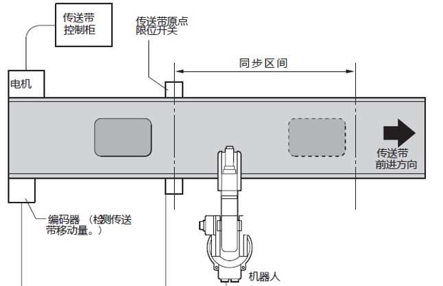
Conveyor Belt Tracking | 11 MB
Download


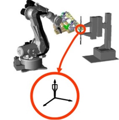
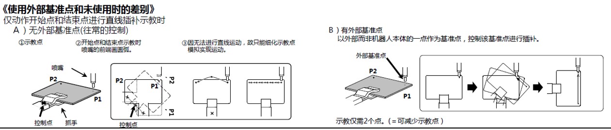
外部基准点功能说明书(英文) | 2 MB
Download
外部基准点功能说明书(英文) | 2 MB
Download

伺服浮动功能说明书(英文) | 2 MB
Download
伺服浮动功能说明书(英文) | 2 MB
Download
伺服浮动功能说明书(英文) | 2 MB
Download
Helical Interpolation | 718 KB
Download